Parts with electrodes and circuits formed on 3D molded resin are called MID(Molded Interconnect Device).
Nissha IME is one of the new construction methods for MID. So, what kind of construction methods does MID have? Here, we introduce the differences between conventional MID methods and Nissha IME.
What is MID?
MID stands for Molded Interconnect Device, referring to parts where electrodes, circuits, and other components are formed on the surface of a three-dimensional molded resin.
With the development of MID technology, it has become possible to form circuits and mount components on three-dimensional shapes, which were previously limited to flat surfaces. This advancement allows for the design of electrical appliances in more complex, three-dimensional shapes, making them thinner, lighter, and smaller.
MID Construction Methods
Conventional MID construction methods can be broadly classified into two types: the double molding method and the single molding method.
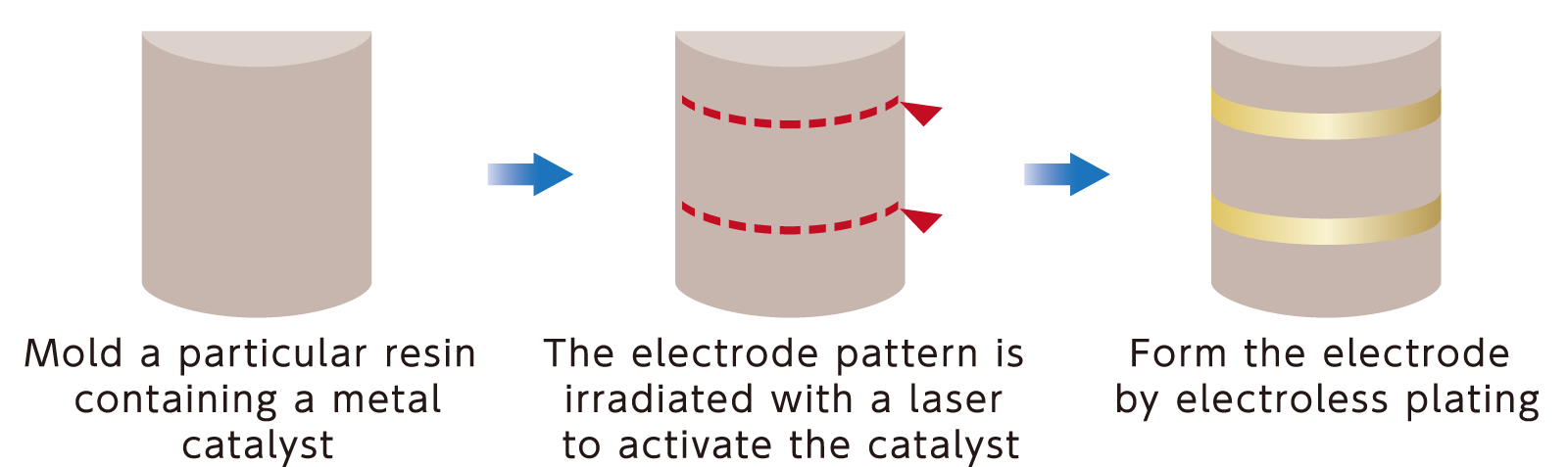
Among these, LDS (Laser Direct Structuring), a typical single molding method, is currently the most widely used.
The LDS method requires the use of specific resins. A laser is used to activate a catalyst in the areas to be patterned, and electrodes are formed by electroless plating.
Molded resins with three-dimensional circuits created by the LDS method are compatible with small electronic devices with limited space. They are often used for antennas, as well as connectors and switches.
Nissha IME is a technology that enables forming electrodes and circuits on three-dimensional molded resin using a method completely different from conventional MID methods. Nissha IME offers many unique benefits and achieves structures that are not possible with traditional methods.
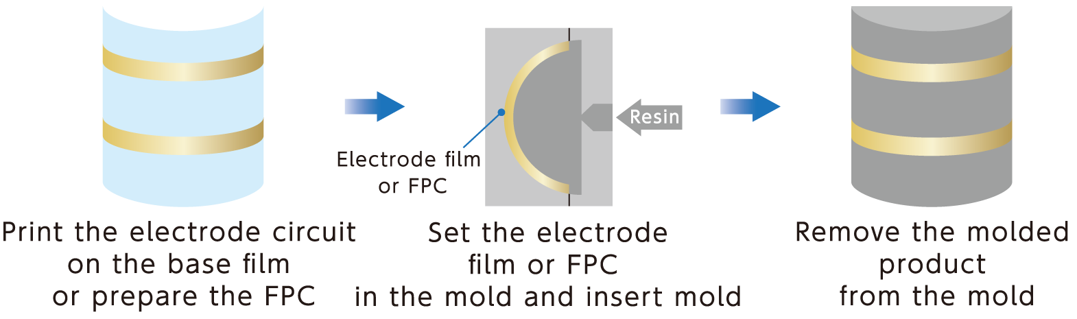
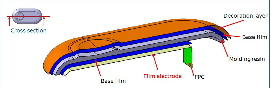
In the Nissha IME method, a film or FPC with printed electrode circuits or sensor patterns is prepared in advance and inserted into a mold for injection molding. This integrates the circuit at the same time as molding the resin product. The density of the circuit can be increased by using a film or FPC with electrode circuits formed on both sides. Additionally, the degree of integration can be further enhanced by incorporating FPCs with pre-soldered electronic components.
●More Freedom in Choosing Molding Resin Material and Color
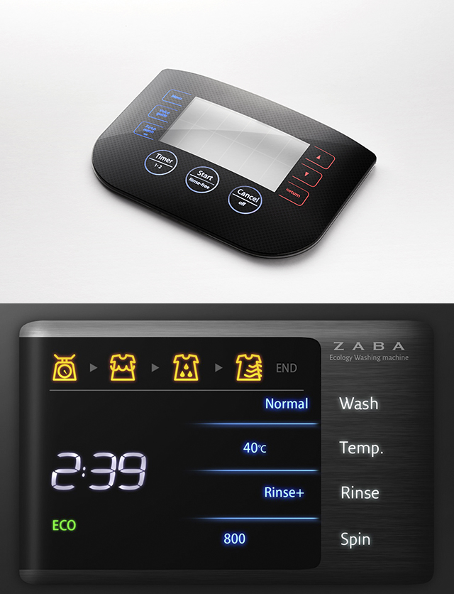
The LDS method requires a specific resin containing a catalyst, making it incompatible with general molding resins and transparent resins. On the other hand, Nissha IME allows the use of general molding resins. You can freely select the material and color of the resin, including transparent options, making it suitable for parts that need to transmit light and designs requiring transparent windows such as displays.
●Selectable Connection Method to PCB
Typically, the LDS method involves contacting the spring pin mounted on the board with the electrode formed by LDS. With Nissha IME, besides connecting with spring pins, you can extend the FPC for insertion and connect it using an FPC connector.
●Unique Shapes by Nissha IME
Nissha IME enables unique shapes that are unattainable with conventional methods.
It allows for the insertion of electrodes inside tubular molded products or deeply drawn shapes.
With Nissha IME, you can choose from multiple combinations of which layer of the part to insert the electrodes into and how they are electrically connected to the board. The position of the electrodes and the method of electrical connection with the board are crucial in product design.
We will propose a combination that suits your needs.
Case 1: Electrode on Front
Pin connecrion

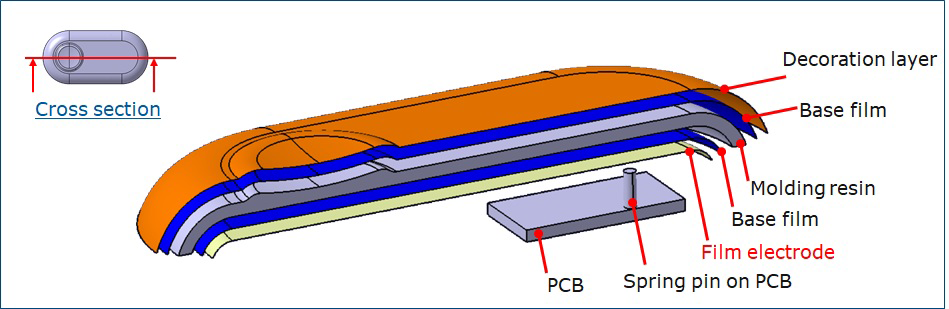
Case 2: Electrode on Back
FPC connecrion
Pin connecrion from PCB
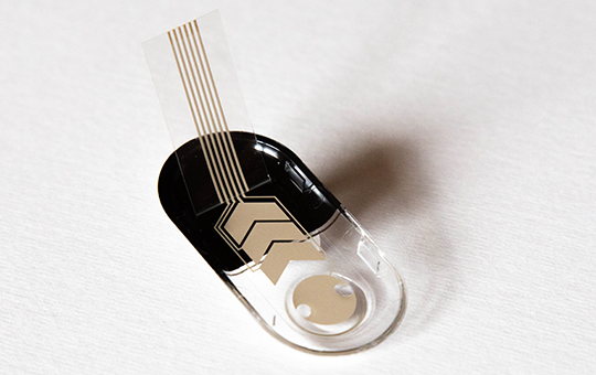
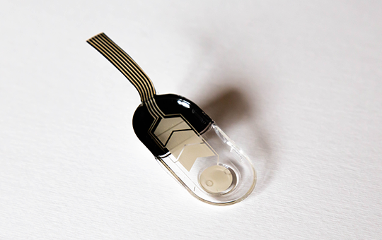
We have actual samples available for you to view. There are multiple structural patterns available.
Please feel free to contact us if you are interested.
Please feel free to contact us.
CLICK